(209) 368-7171 [email protected]

Applications


Solving the Most Demanding Applications in the Power Generation Industry

Today, now more than ever, the strain on a Power Generation plant and its team can feel enormous at times. Set aside the obvious danger of the job, let’s look at the operational pressures. Most likely, you are dealing with aging equipment, budget restraints, operational efficiency requirements, new regulations, and limited maintenance downtime. Add an unexpected outage due to a malfunctioning machinery to the mix, and your blood pressure has skyrocketed.

What the average energy consumer doesn’t realize is that it takes a vast amount of work needed to plan, execute, and maintain a power generation plant. The electricity that comes through the little outlet on the wall takes a lot of work. All they’re worried about is whether their newest gadget charges properly.

What you need is a partner, someone who understands the ins and outs of the power generation plant. Someone who will listen and help you solve the most pressing of problems at the plant, whether it be a cracking expansion joint that your hoping will hang on until the next scheduled outage or a turbine not working at an high efficient level.

Holz Rubber Understands Your Challenges and is Here to Help.

See, it isn’t about selling more products. It is about being a reliable, customer-centric partner that provides the technical know-how to solve some of your most daunting problems.

Let’s be honest, you probably don’t go home and dream about expansion joints, but we do. We know the ins and outs of how expansion joints work in a power generation plant. Also, we know what it means to you to have the right product in the right location without worrying about unexpected outages. The Holz Rubber team recognizes your budget restraints, and we work with you to provide the highest quality product for each application.

Here is how we can help in various areas of the plant:

Holz Rubber Power Generation Steam
Since temperatures are above flue gas dew point temperature in the Air Inlet, a chemical barrier is not needed. A composite should be used, as well as a pillow to eliminate the possibility of mechanical damage due to flutter.

Expansion Joint Specifications
  • Temperature: 600°F to 750°F
  • Media: Clean air from air heater air outlet
  • Particulate: Minimal
  • Operation: After start up movement is nominal; Severe high pressure operating conditions may be experienced in the primary air ducts of positive pressure boilers
  • Pressure: Positive 5″ water column to as high as 80” water column for positive pressure boilers
  • Movements: High temperatures will generate moderate compressive movements; Each change in direction in the ductwork will generate a resultant lateral offs
  • Insulation/Lagging: Do not lag over the expansion joint; Also, remove lagging from flanges to allow radiant cooling
  • Expansion Joint Recommendation: Flue Duct Expansion Joint should be used.
Combustion Turbine, also known as gas turbine, exhaust systems are extremely difficult application. As such, several specifics are considered in determining the best solution for optimal life of an expansion joint.

Design Considerations

Type of frame to duct/equipment connection:

  • Hot to hot – requires insulated equipment on both sides of the breach opening
  • Hot to cold – requires turbine side is externally insulated and the downstream side is internally insulated
  • Cold to cold = requires both turbine side and downstream side are externally insulated

Duct configuration – round, square or rectangle

Flow direction – horizontal, vertical or angled

Location with respect to flow directional change

Proximity of the bottom of the expansion joint to the ground. Radiated heat can prematurely damage the outer cover

Turbine manufacturer – model, rated flow, temperature and pressure

Materials of construction for the following components must be compatible with the system operating conditions:

  • Frames
  • Pillows (when and where used)
  • Belts
  • Internal flow liners must allow for movement as well as flow protection of the pillow(s)
Expansion Joint Specifications
  • Temperature: 1000°F – 1500°F Excursions 1650°F
  • Media: Hot exhaust gas from combustion of natural gas or fuel oil. Dry and non-corrosive
  • Pressure: Constant positive pressure generally no higher than 20″ Water Gauge; Very turbulent environment
  • Operations: Typically online for 12 to 18 months; Power peaking plants may cycle frequently as much as once per day
  • Movements: Large compression rating due to the temperature; Lateral movements typically 1″ or lower due to short direct ductwork runs
  • Expansion Joint Recommendation: High Temperature Expansion Joint – Holz Series 1000HTF or 12000HTFW should be used
A diverter, when used is a devise that is installed downstream of the GT exhaust flange. It can be installed early in the construction phase to allow for early turbine running in simple cycle prior to tie in to the HRSG and Steam Turbine. It serves the function of allowing the HRSG to be brought on line slowly or to be by-passed completely for routine maintenance.

Diverters generally have three (3) ports and all three have expansion joints. These ports are designed as “Cold to Cold” flange arrangements. The bypass portion runs to a silencer and then to a stack. Often times a silencer is incorporated within the stack above the diverter and is supplied as a single package.

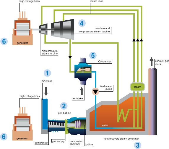
Hot exhaust gas exits the gas turbine at temperatures greater than 1000°F and then passes through the Heat Recovery Steam Generator (HRSG). In the HRSG, there are multiple layers of tubes, filled with high purity water (from the condenser). This water is converted to high temperature steam as the exhaust gasses pass over the tubes. The steam is then directed to the steam turbine and the spent steam is sent back to the condenser to start the cycle over again.

Expansion Joint Specifications
  • Temperature: 1000°F – 1500°F Excursions 1650°F
  • Media: Hot exhaust gas from diverter
  • Pressure: Constant positive pressure generally no higher than 20″ Water Gauge
  • Operations: Typically online for 12 to 18 months; power peaking plants may cycle frequently as much as once per day
  • Movements: Large compression rating due to the temperature
  • Expansion Joint Recommendation: Holz Series 1000HTF or 12000HTFW High Temperature Expansion Joint
The primary purpose of a surface condenser is to condense the exhaust steam from a steam turbine to obtain maximum efficiency and also to convert the turbine exhaust steam into pure water so that it may be reused in the steam generator or boiler as boiler feed water.

After the steam is spent in the turbine process, the residual steam leaves the turbine at low pressure and low heat. The purpose of the condenser is to turn low energy steam back into pure water for use in the HRSG. Typical condenser expansion joints are located at the condenser and/or at the recirculating pumps.

Holz recommends its Series 320M Molded Piping Expansion Joint or Series 320 Hand-Built Pressure Piping Expansion Joint should be used.

Design Considerations
  • Since temperatures are above flue gas dew point temperature during continuous operation, the system will be dry and chemical barriers are not needed
  • A composite should be used
  • Use of a pillow will eliminate the possibility of mechanical damage due to flutter

Expansion Joint Specifications
  • Temperature: 600°F – 750°F
  • Media: Clean air from air heater air outlet
  • Particulate: Minimal
  • Pressure: Positive 5″ water column to as high as 80″ water column for positive pressure boilers
  • Operations: After start up movement is nominal; Severe high pressure operating conditions may be experienced in the primary air ducts of positive pressure boilers
  • Movements: High temperatures will generate moderate compressive movements; Each change in direction in the ductwork will generate a resultant lateral offset
  • Insulation/Lagging: Do not lag over the expansion joint; Also, remove lagging from flanges to allow radiant cooling
  • Expansion Joint Recommendation: High Temperature Expansion Joint should be used
Design Considerations

  • Due to pressure pulsations and extreme turbulence a flow liner may be required
  • If abrasion or high velocity flow is anticipated, a flow liner should be used
Expansion Joint Specifications
  • Temperature: -20°F – 120°F
  • Media: Dry ambient clean air
  • Particulate: None
  • Pressure: Positive pressure ranging from 30″ to 90″ water gauge; Fan outlets may produce pressure pulsations or extreme turbulence
  • Operations: Operational and cyclical conditions have very little effect on the air side ducts
  • Movements: Fan outlet sees little movement, primarily vibration
  • Insulation/Lagging: Low temperatures allow lagging over the expansion joints without adverse effects
  • Expansion Joint Recommendation: Flue Duct Expansion JointHolz Series 945 Maximum Movement should be used
In the Air Pre Heater Air Outlet flue gas from the boiler passes through the basket on the “hot side” and transfers the heat into the materials of the basket “steel.” The basket rotates to the “cold side” in which the primary air fan forces ambient air through the hot basket resulting in preheated air that is routed to the coal pulverizers.

Design Considerations
  • Since temperatures are above flue gas dew point temperature, a chemical barrier is not needed
  • A composite should be used
  • Use of a pillow will eliminate the possibility of mechanical damage due to flutter
  • Flow liner required

Expansion Joint Specifications
  • Temperature: 600°F – 750°F
  • Media: Relatively clean air
  • Particulate: Minimal
  • Pressure: Positive 5″ water column to as high as 80″ water column for positive pressure boilers
  • Operations: After start up movement is nominal; Severe high pressure operating conditions may be experienced
  • Movements: High temperatures will generate moderate compressive movements; Each change in direction in the ductwork will generate a resultant lateral offset
  • Insulation/Lagging: Do not lag over the expansion joint; Also remove lagging away from flanges to allow radiant cooling
  • Expansion Joint Recommendation: High Temperature Expansion Joint – Holz Series 600HTF should be used
Design Considerations
  • Due to pressure pulsations and extreme turbulence a flow liner may be required

Expansion Joint Specifications
  • Temperature: -20°F – 120°F
  • Media: Ambient Air from primary fan
  • Particulate: None
  • Pressure: Positive 5″ water column to as high as 80″ water column for positive pressure boilers
  • Operations: Operational and cyclical conditions have little effect on the air side ducts
  • Movements: Primarily vibration
  • Insulation/Lagging: Low temperatures allow lagging over the expansion joints without adverse effects
  • Expansion Joint Recommendation: Flue Duct Expansion JointHolz Series 945 Maximum Movement should be used
Heat exchangers are used to capture the last bit of usable heat from the boiler gases and transfer the energy to the boiler feed water tubes. This raises the temperature of the feed water to the boiler, in turn reduces the energy required to meet boiler output.

Design Considerations
  • Since temperatures are well above flue gas dew point during continuous system operation, the system will be dry and chemical barriers are not needed
  • If operation is cyclical, dew point may be reached allowing corrosive condensates to form; The use of a belt element with a chemical film barrier will eliminate the resulting corrosion
  • Due to large movements a tabbed pillow should be utilized; The pillow also will eliminate the possibility of mechanical damage due to flutter
  • Ductwork should be cold offset to minimize movements
  • Overlapping flow liners required
  • This design inhibits direct impingement of the flyash

Expansion Joint Specifications
  • Temperature: 700°F – 900°F Excursions to 1200°F
  • Media: Low PH flue gas from the combustion of coal
  • Particulate: Heavy fly ash particulate from coal combustion
  • Pressure: Slightly negative for balanced draft boilers, otherwise positive pressure as much as 40″ – 50″ water gauge
  • Operations: Systems usually on line for 12-18 months
  • Movements: Large expansion which requires joint systems with large lateral and compression capabilities
  • Insulation/Lagging: Do not lag over the expansion joint. Also remove lagging away from the flanges to allow radiant cooling
  • Expansion Joint Recommendation: High Temperature Expansion Joint – Holz Series 1000HTF or 1200HTF should be used
Design Considerations
  • Use of a pillow will inhibit direct impingement of the fly ash that will be present
  • A composite should be used
  • Flow liner required

Expansion Joint Specifications
  • Temperature: 300°F – 400°F; Excursions to 600°F
  • Media: Low PH flue gas from the combustion of coal
  • Particulate: Heavy fly ash particulate from coal combustion
  • Pressure: Slightly negative for balanced draft boilers, otherwise positive pressure as much as 40″ – 50″ water gauge
  • Operations: Systems usually on line for 12-18 months
  • Movements: Moderate movements due to reduced temperatures
  • Insulation/Lagging: Do not lag over the expansion joint; Also, remove lagging away from flanges to allow radiant cool
  • Expansion Joint Recommendation: High Temperature Expansion Joints – Holz Series 600HTF should be used
Design Considerations
  • Must consider the possibility of dew-point (wet condition). A PTFE gas barrier can be added for increased chemical resistance
  • Flow liner required when using a PTFE product

Expansion Joint Specifications
  • Temperature: 280°F – 350°F; Excursions to 600°F
  • Media: Flue gas from precipitator drawn by induced draft fan
  • Particulate: Minimal after ESP
  • Pressure: Negative pressure as much as 15″ water gauge
  • Operations: Although movements are not severe. Temperatures will approach dew point and present potential corrosion problems
  • Movements: Moderate compressive and lateral movements expected depending on ductwork configurations and lengths
  • Insulation/Lagging: Low temperatures allow lagging over the expansion joints without adverse effects
  • Expansion Joint Recommendation: High Temperature Expansion Joint
Design Considerations
  • Temperatures are just above dew point so designs must consider a wet environment. A PTFE gas barrier can be added for increased chemical resistance
  • Many Induced draft fans utilize small dual inlets with control or shutoff dampers. Designs must not interfere with damper blades
  • Flow liner is required when using a composite.

Expansion Joint Specifications
  • Temperature: 280°F – 350°F
  • Media: Flue Gas from Precipitator
  • Particulate: Minimal
  • Pressure: Negative pressure, as much as 15″ water gauge
  • Operations: Although movements are not severe temperatures will approach dew point and present potential corrosion problems
  • Movements: Fan joints usually see minimal movement, primarily vibration
  • Insulation/Lagging: Low temperatures allow lagging over the expansion joint without adverse effects
  • Expansion Joint Recommendation: Depending on fan configuration a Flue Duct Expansion Joint – Series 945 Maximum Movement or a High Temperature Expansion Joint – Series 600HTF should be used.
Design Specifications
  • Temperatures are just above dew point so designs must consider a wet environment; A PTFE gas barrier can be added for increased chemical resistance
  • Many Induced draft fans utilize small dual inlets with control or shutoff dampers; Designs must not interfere with damper blades
  • Flow liner is required when using a composite

Expansion Joint Specifications
  • Temperature: 280°F – 350°F
  • Media: Flue Gas from Precipitator
  • Particulate: Minimal
  • Pressure: Negative pressure, as much as 15″ water gauge
  • Operations: Although movements are not severe temperatures will approach dew point and present potential corrosion problems
  • Movements: Fan joints usually see minimal movement, primarily vibration
  • Insulation/Lagging: Low temperatures allow lagging over the expansion joint without adverse effects
  • Expansion Joint Recommendation: Depending on fan configuration a Flue Duct Expansion Joint – Holz Series 945 orHigh Temperature Expansion Joints – Holz Series 600HTF should be used
The wet scrubber is a vessel (also called an absorber) that contains a sorbent solution that is injected into and saturates the flue gas stream as it passes through the absorber. The sorbent is alkaline to neutralize the SO2 that is present in the flue gas. Flue gas ductwork just before and after the absorber module will normally be constructed of a corrosion resistant alloy since the gas temperature has been reduced to below dew point and may contain residual acid.

Design Considerations
  • Membrane may see more flexing than in other applications, good flexibility is needed

Expansion Joint Specifications
  • Temperature: 280°F – 330°F
  • Media: Flue gas
  • Particulate: Minimal before scrubber system
  • Pressure: Slightly negative for balanced draft boilers, otherwise positive pressure as much as 40-50 inches water gauge
  • Operations: Although movements are not severe temperatures will approach dew point and present potential corrosion problems
  • Movements: Small movements expected
  • Insulation/Lagging: Low temperatures allow lagging over the expansion joint without adverse effects
  • Expansion Joint Recommendation: Depending on scrubber configuration, use a Flue Duct Expansion Joint – Holz Series 945 Maximum Movement or a High Temperature Expansion Jointshould be used
Wet scrubbed flue gas has a high moisture content and low dew point resulting in condensation which causes vapor plume and the formation of acidic mist in the stack. To prevent this acidic mist, some plants install flue gas re-heaters to delay condensation until the gases rise higher into the atmosphere.

Design Considerations
  • Temperatures are in or near the flue gas dew point, the system will be wet during continuous operation; A chemical barrier should be used
  • Membrane may see more flexing than in other applications, good flexibility is needed
  • Partially open Bypass Dampers or changes in direction of ductwork may create excessive gas stream turbulence resulting in direct flue gas impingement

Expansion Joint Specifications
  • Temperature: 150°F – 350°F; Excursions to 600°F
  • Media: Wet scrubbed flue gas from scrubber
  • Particulate: Negligible after scrubber system
  • Pressure: Pressure varies from positive to negative depending on system operation. Up to 15″ water gauge
  • Operations: Although movements are not severe temperatures will approach dew point and present potential corrosion problems; Scrubber service is highly corrosive
  • Movements: Small movements expected
  • Insulation/Lagging: Low temperatures allow lagging over the expansion joints without adverse effects
  • Expansion Joint Recommendation: Flue Duct Expansion Joint – Holz Series 945 Maximum Movement or a High Temperature Expansion Joint should be used
Wet scrubbed flue gas has a high moisture content and low dew point resulting in condensation which causes vapor plume and the formation of acidic mist in the stack. To prevent this acidic mist, some plants install flue gas re-heaters to delay condensation until the gases rise higher into the atmosphere.

Design Considerations
  • Since temperatures are above flue gas dew point, the system will be dry during continuous operation; However, if changes in system operation or frequent outages cause wet, corrosive conditions, an optional chemical barrier should be considered

Expansion Joint Specifications
  • Temperature: 350°F – 500°F; Excursions to 600°F
  • Media: Scrubbed Flue Gas (Wet)
  • Particulate: Negligible
  • Pressure: Pressure ranges from slightly negative to slightly positive, -5″ to +5″ water gauge
  • Operations: Although movements are not severe. Temperatures will approach dew point and present potential corrosion problems
  • Movements: Small movements expected
  • Insulation/Lagging: Moderate compressive and lateral movements expected depending on ductwork configurations and lengths
  • Expansion Joint Recommendation: depending on Re-Heater configuration, use a High Temperature Expansion Joint – Holz Series 600HTF should be used
The Chimney is where the flue gas is vented into the outside atmosphere.

Design Considerations
  • Temperatures are in or near the flue gas dew point; Chemical barrier should be considered.
  • Flow liner required

Expansion Joint Specifications
  • Temperature: 120°F – 180°F
  • Media: Scrubbed Flue Gas (Wet)
  • Particulate: Negligible
  • Pressure: Depending on unit load and weather conditions pressure ranges from slightly negative to slightly positive, -5″ to +5″ water gauge
  • Operations: Although movements are not severe. Temperatures will approach dew point and present potential corrosion problems
  • Movements: Moderate movements expected. Good flexibility needed
  • Insulation/Lagging: Low temperatures allow lagging over the expansion joint without adverse effects
  • Expansion Joint Recommendation: depending on the application, a High Temperature Expansion Joint should be used

Related Application Data Sheets

Splicing Instructions Saves Power Station Time & Money

Electrostatic-precipitator-inlet-expansion-joint-thumbnail-125x175An electrostatic precipitator (ESP) is a large industrial emission-control unit that uses a fabric expansion joint on both the inlet and outlet. An ESP traps and removes dust particles from exhaust gas stream by using an electrostatic charge.
Read more…

Expansion Joints Designed to Prevent Hurricane Damage in Gas Turbine Air Inlet

Gas-turbine-inlet-expansion-joint-thumbnail-125x175Gas turbines require a lot of intake air to function properly. As the ambient air is drawn into a Filter House, the air passes through a series of cleaning filters. Next, this large volume of air passes through a Silencer section to quiet the noise before entering into the Turbine Inlet.
Read more…

Settled Ground Creates Breach Opening at Coal Fired Plant
Settled-Ground-at-WY-Coal-Fired-Power-Plant-Cover-Art-125x175The customers’ scrubber piping has settled over the years which caused the breach opening to lengthen approximately 1 1/4″ from the installed opening. This amount of additional opening caused the rubber to separate from the reinforcement ply on the outer cover of the expansion joint.
Read more…

Technical Knowhow Helps Power Plant Improve Turbine Performance

Midwest-Power-Generation-Cover-Art-8-6-15A Midwest power plant was struggling with a failing expansion joint. Cracks and tears close to the corners were causing a loss of air to the turbine during operation. This loss of air causes turbine efficiency related problems.
Read more…
Have a question about your specific application?